Application
The cables are fully filled with petroleum jelly, being designed for use in access or trunk networks, from telephone exchange to subscriber area. The cables are suitable for installation in ducts and direct burial in the ground.
Normes

• CW1236
Construction
Conductors
Solid annealed bare copper 0.32/0.4/0.5/0.63/0.9mm as per class 1 of BS 6360/IEC 60228
Isolation
Cellular polyethylene as per BS 6234/BS EN 50290-2-23/IEC 60708
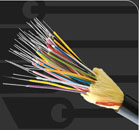
Twisted Pairs
Insulated conductors are twisted into pairs with varying lay length to minimize crosstalk
Elément de câblage
Twisted Pairs
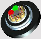
Cable Core Assemblée
Cables with up to 100 pairs are composed of 25-pair units or 12/13-pair units; cables with over 100 pairs are composed of 25, 50 or 100-pair units cabled together. Any extra pairs form a separate unit. Units are identified by colour coded binders. Standard construction is per CW 1236 given in Cable Make Up Diagram
Core Wrapping
One or more non-hygroscopic polyester tapes are helically or longitudinally laid with an overlap. These tapes furnish thermal, mechanical as well as high dielectric protection between shielding and individual conductors
Moisture Barrier(optional)
An optional aluminium tape (0.15mm) coated with PE-copolymer on one or both sides is applied longitudinally with overlap over the cable core to provide 100% electrical shielding coverage and ensures a barrier against water vapor
Remplissage
The cable core interstices are filled with petroleum jelly to avoid longitudinal water penetration within the cable. The water resistant filling compound is applied to the air space between non-hygroscopic tape and shield, shield and sheath within the cable core
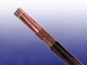
Gaine
Black low density polyethylene as per BS 6234/IEC 60708, being able to withstand exposure to sunlight, temperature variations, ground chemicals and other environmental contaminants
Ripcord
Ripcord may be provided for slitting the sheath longitudinally to facilitate its removal
Spare Pairs (optional)
Spare pairs may be incorporated for 200 and larger pair cables
Continuity Wire (optional)
One tinned copper drain wire may be longitudinally laid to ensure electrical continuity of the screen
Facultatif Construction
Câble armé
Steel wire armour or corrugated steel tape armour is applied over an optional inner polyethylene sheath. For steel tape version, the 0.15mm thick steel tape is coated with a copolymer and applied with an overlap. An outer polyethylene sheath is applied over the armour


Electrical Properties
*Mutual capacitance values for 0.63mm & 0.9mm may be increased by 3% for cables with a nominal number of pairs less than 400.
Mechanical and Thermal Properties
Temperature range during operation (fixed state): -30°C – +70°C
Temperature range during installation (mobile state): -20°C – +50°C
Minimum bending radius: 10 x Overall Diameter (unarmoured cables);15 x Overall Diameter (armoured cables)
Colour Code
Standard colour code is per CW 1236 given in Colour Code Chart
1 2